• Pardon the dust while the boys rebuild the site.

    The board will be in a state of disarray as I get things sorted out, for a little while at least.

    The new incarnation is using Xenforo as the system software. It is much like what we are used to, with a few differences. I will see about making a FAQ to help point out the differences for the members.


    One IMPORTANT difference for all of us old timers is that the 'mail' system is replaced with what are called 'conversations'/

    There is no 'Inbox' or 'Out box' or 'Sent' folders anymore.

    Think of Conversations as private 'threads' or topics that don't exist in a forum, that you start with another member. NOTE: Conversations can include more than one member if you or someone else in the conversaion, likes.
    Takes a little getting used to but I am sure you all can get a hang of it.


    Only a slightly modified default default Xenforo style is available for now. Once the new SAG style is ready it will be available.

    All existing users should be able to login with their usernames and passwords once the site goes up.


    If anyone has difficulties logging in please contact me at sixthvanguard@gmail.com.


    Thank you for your support and patience. I know it has been a loooong road.

Knife Edge Wire Obstacle

Jhtrickey3

Tanker
Ever since I viewed the "Making 1/6 scale barbed wire" tutorial on this site:
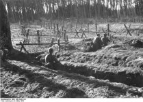
http://www.sixtharmygroup.com/forums/showthread.php?t=10675 and the great method that Dudulle.69 used to create his wire I have wanted to create a wire obstacle. The "Knife edge" obstacle gave me a chance to do this. Many of you will recognize the obstacle, but perhaps not by this name.


The materials for this are quite simple and I found them all at local crafts stores (Hobby Lobby and Michaels). Hobby Lobby has a good source for the wooden dowels offering a good select in both 3/4" diameter and 5/8" diameters. For this project I went with a 3/4" diameter as this felt right.


Materials:
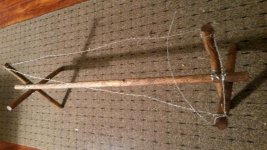
(4) 3/4" dowel rods 12" long. (these were cut down to 11" long)
(1) 3/4" dowel rod 36" long. (this was cute down to 30" long)


The above measurements were used to attempt to replicate the dimensions on the diagrams, but obviously you could replicate any length or height.


For the wire, I used 26 gauge wire. To create the barbs, the 26 gauge wire was wrapped around a piece of 18 gauge wire. In this matter, I tired to follow Dudulle.69's barbed wire making method.


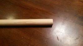
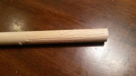
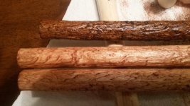
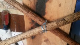
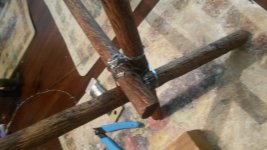
The first step was to prep the wooden dowels to get them to resemble more finished poles that would be mass produced. A simple method that I used was to used a small round cutting bit in a dremel tool and "score" the length of the dowel to create a textured finish. After some time, you can get a good pole that has some decent texture and no longer resembles a store bought wooden dowel.
 

Attachments

  • Knife Edge.gif
    Knife Edge.gif
    13 KB · Views: 319
  • Knife Edge - 01.jpg
    Knife Edge - 01.jpg
    94.5 KB · Views: 117
  • Knife Edge - 02.jpg
    Knife Edge - 02.jpg
    96.3 KB · Views: 126
  • Knife Edge - 03.jpg
    Knife Edge - 03.jpg
    96.5 KB · Views: 130
Re: Knife Edge Wire Obstacle - Part II

Once the wooden dowels are textured, I applied several coats of wood stain to get a color that I thought looked right. I used a color called English Chestnut for those interested.


The next step was to assemble the cross pieces and hold them together with wire. This proved a little easier said than done. I gave this several attempts as I did not want the support to have TOO much wire support. The question became how much was enough. One thing that did come in handy was the 18 gauge wire. Cutting this wire into appropriate lengths and bending it into right angles, I was then able to drill holes in the wooden dowels and provide wire wrapping points for the 26 gauge wire that secured the two dowels together to form the "x".


In using my base diagram and working out the approximate 1/6 scale distance for 1.2 meters, I came up with roughly 8" as my working distance.


I first drilled a hole through the center of both dowels at the 5 1/2" mark and then used my 18 guage wire to secure that pivot point. Now the "fun" part. Moving the two dowel into an "x" with the base about 8" apart, I took my 26 gauge wire and wove a figure "8" pattern.


When I was done, this was still somewhat loose. I added a second oval wrap around the poles to give it some more strength and support. Be careful to watch the distance. I again used the 18 gauge wire drilled into the wooden dowels and bent to support and tighten the wire bands on the poles. This "felt" structurally right, but I am sure that it can probably be improved upon.
 

Attachments

  • Knife Edge - 04.jpg
    Knife Edge - 04.jpg
    93.5 KB · Views: 121
  • Knife Edge - 05.jpg
    Knife Edge - 05.jpg
    91 KB · Views: 110
Re: Knife Edge Wire Obstacle - Part II

The next step was again something of a trail and error approach to securing the cross pole into the two "X" members. After several false starts, I finally got a method that was not too wire heavy and also firmly secured the entire structure together.


Laying the long pole into the cross members, I first used a simple oval loop between one of the "X" uprights. I secured and tighten this with the 18 gauge wire pegs.


I then ran a second oval loop around the other "x" member upright and secured that as well. When both sides were done, I still had my 8" distance on the "x" members and a secure structure that was not going to fall over or twist out of place. Again, I am sure that some others on here could probably come up with a better method of securing the wooden poles to one another.


The final step (and one that I am still working on) is weave the barb wire through the completed obstacle. Per the initial diagram, this seems to be a series of triangles that go across the length, over the side "x" member, then back to the staring point on a diagonal to complete the triangle. A lot of wire. I will post the finished project when I am complete.


-joe
 

Attachments

  • Knife Edge - 06.jpg
    Knife Edge - 06.jpg
    90 KB · Views: 127
  • Knife Edge - 07.jpg
    Knife Edge - 07.jpg
    100 KB · Views: 192
As far as I can tell, most armies knew of this construction in one form or another. Was reading one site that was (I believe) based on French engineers that referred to this as the "English Knife's Edge" or "Spanish Saddle".


I did find some version in Poland during the uprising and also in France during the invasion. Below image is German. My best guess is that this was a common engineering build of the day. Used to seal off entrances or pathways through other fixed wire obstacles. This being something that could be "easily" moved. There is a good shot of European countryside (had to be a frontier) with rows of fence and wire, with a Knife edge obstacle running across the road.


(winter image is Finnish soldiers)


-joe
 

Attachments

  • Bundesarchiv_Bild_146-2006-0187_Westwall_im_Bienwald_Laufgraben_und_Drahtverhau.jpg
    Bundesarchiv_Bild_146-2006-0187_Westwall_im_Bienwald_Laufgraben_und_Drahtverhau.jpg
    92.2 KB · Views: 114
  • 1st_inf_p22_image001_barbedwire.jpg
    1st_inf_p22_image001_barbedwire.jpg
    16.2 KB · Views: 100
  • making barbed wire obstacles.jpg
    making barbed wire obstacles.jpg
    67.8 KB · Views: 228
Hallo!


I think maybe that may be a translation issue? I know them as Spanish Riders or "Knife Rests." (The "rest" coming from the table ware knife rest.)


For WWII they seem to be mostly movable barbed wire barriers. For WWI, they were great for pulling down into a trench to "inconvenience" attackers.
 
Kurt - yes.. You are correct.. Knife's rest. I probably need to get more rest!!!!


The WWI descriptions with some of the variations were interesting.. Including one that was used to deflect grenades thrown into trenches.


(sorry for the slow response in getting this done.. the wire part is tedious)


-Joe
 
Back
Top